Showing posts with label Network Problem Troubleshooting. Show all posts

Procedure On Sharing Globe Tattoo Internet Connection In A Local Area Network

You may be looking for some ways on how to share an internet connection using your globe tattoo or Smartbro broadband kit. The procedure is relatively simple. Just some few knowledge in networking and be able to follow simple yet detailed instructions. Sharing an internet connection using either globe tattoo or Smartbro WiFi kit has been a common practice by most "technically" inclined techies to be able to save on the cost of loading and individual purchasing of the WiFi kits.

However, there are several things to have to be able to share an internet connection using your Globe tattoo and Smartbro WiFi kits. Cables, computers, and of course the proper configurations. Let me also encourage (specially the newbies) to make some reviews on how to setup a home network and configuring ip's for LAN. So here is the tutorial for you so you can start sharing your internet connection via globe tattoo and Smartbro.


Things Needed For Globe Tattoo / SmartBro Internet Sharing

Several networked computers or at least two (OS : XP, Vista, or Win 7)
A Globe tattoo or SmartBro Wifi Stick


Procedure On How To Do Internet Sharing With Your Globe Tattoo or SmartBro Wifi Stick

1. First, you must have your computers have a network. To start with this, follow this procedure on how to setup a home network.

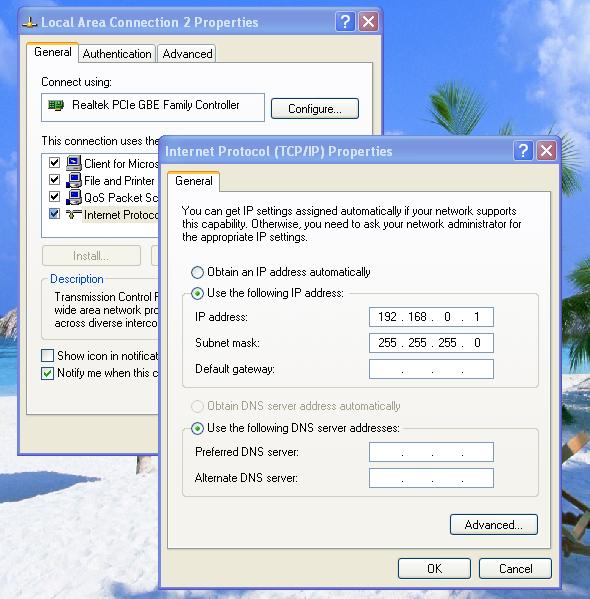
2. Once you have completed the networking procedure, we need to change the ip for computer with the internet connection. The computer that has Globe Tattoo or SmartBro dashboard installed SHOULD have an ip of 192.168.0.1 to serve as the gateway for the rest of the computers that are connected in your network.

To do this, go to "Control Panel" choose "Network Connections" and click right on the "Local Area Connection" and choose "Properties" and under the "General" tab highlight "Internet Protocol (TCP/IP)" and click on the "Properties" button. Do the same configuration like shown below.


Globe tattoo configuration for lan internet sharing image


For the rest of the computers in the network, have the configuration as shown below (use 192.168.0.2 , 192.168.0.3 , 192.168.0.4 and so on... for the rest of the computers). Please use the ip of the computer that we did a setup earlier as the gateway ip for the rest of the computers. Use the configuration as shown below.


Globe tattoo configuration for lan internet sharing on client computers image


3. Once you got to the "Network Connections" window, click right on "Globe Broadband - Prepaid" network icon and choose "Properties" then go to "Advanced" tab. Check the box under "Internet Connection Sharing" that says "Allow other network users to connect..." Just click "ok" and see to check your configuration below.


globe tattoo and smartbro internet sharing


Configuring to Share Internet Connection with Globe Tattoo image


4. Disconnect and reconnect your Globe Tattoo or SmartBro dashboard and test if the computers in your network already has a shared internet connection. If you ran over a problem, please check if your browsers are configured to use proxies. Please disable the proxies. And also consider checking the gateway ip of the connected computers.


This is the procedure on how to share internet with Globe Tattoo or SmartBro. Though this example is for Windows XP, the procedure with WIn 7 and Vista is very similar. Our setup is currently running with eight computers all connected to a switch. We also tried running proxy servers on Globe tattoo but we need to configure each networked computers with the same proxy as the gateway computer is connected on. Who says you can't run VPN connections using either Globe Tattoo or SmartBro to be shared in a network, well try it yourself - it does work with us!
How to Setup a Home Network

Networking home computers is quite a tedious task if you are not familiar with it. Setting up a home network with xp, vista, or win 7 seems difficult but actually it is simple. We will be discussing on how to setup a home network using xp and following networking with the xp procedure in this tutorial is simply similar to that of networking vista and windows 7.

Procedure with networking XP computers is relatively easy. If you will be setting up a network involving two computers, a crossover cable and some xp networking wizard procedure will do the job. Same procedure will work well if you will be setting up a home network for windows vista and windows 7 computers.

Networking with Xp will start by crimping your first or probably not your first crossover network cable (xp networking may sometimes be addicting!). All you need to have is a crimping tool, a length of UTP cable, and an RJ45 jack. Crimping a crossover cable has been previously discussed in our crimping straight through and crossover cable topic. Ok we'll do detailed xp networking and let us start with the materials.


What You Will Need For Setting Up an XP Network

A length of unshielded twisted pair (UTP) cable

2 or 3 RJ45 jacks (better have 2 or more spare jacks)

A network cable tester

Crimping tool


Procedure in Setting Up A Home Network With 2 Computers

1.Create a crossover cable by following the crimping a network cable procedure. This is the very start on setting up a home network. Knowing how to make network patch (straight through cable) and crossover cable is essential for xp networking or setting up a home network.

2. After having crimped your own crossover cable, plug in one end of the crossover cable in one of the computers' Ethernet port or network port and the other end to the other computer's network port. If however you are using a network switch, then you should be using straight through cables.


Setting up a home network using XP image

3.Now go to "Control Panel" and navigate to "Network Connections" (Alternately, instead of going the control panel you can go to "My Computer" and navigate to "My Network Places"). You should be seeing "My Network Places" window with no items on the file display pane.


XP networking wizard image

4. As the window opens, click "Setup a home or small office network" and follow the xp networking wizard as shown in the image above. Just click "Next". This is the beginning of setting up an xp home network on one computer. We will be doing this whole procedure to the second computer.


Internet connection method selection on XP image

5. You will then be prompted on what best describes your computer should behave in a home or office network that you are going to setup. Choose "Other" and click "Next".


XP home network internet connection method image

6. The next window will describe how your computer should fit in the description pertaining to the internet connection and the network itself. If this computer is directly connected to the internet and you are planning to let the other computers in your network to "get" or establish an internet connection through this computer, then choose the first option as shown above and click "Next".


Networking wizard on computer name and description image

7. This will let us tell about the name of our computer in the network. Fill up the computer's description and the computer name. You may choose your own description and name as "computer station 1" and "inuyasha" instead of using "technisize computer1" and "technisize". After filling, just press "Next".

On the other computer that we are also setting up an XP home network, do not use the same computer description and name or else you will have problems with configuring and setting up a home network. Be creative.


Network workgroup name in XP image

8. We are almost halfway of xp networking, let us now give a workgroup name for the network that we are setting up. In the image above, we gave the workgroup name as "Technisize", you can change this to whatever you like and click "Next".


REMEMBER : on the second computer that we are setting up a network, use THE SAME WORKGROUP NAME. If you fail to put the same workgroup name, your computer will NEVER "see" each other in the network.


Configuring file and printer sharing on xp network image

9. The next window will let us decide on file and printer sharing. Of course we may want to let our computers share files on the network right? So go choose "Turn on file and printer sharing" option and click "Next".


XP network wizard automatically configuring image

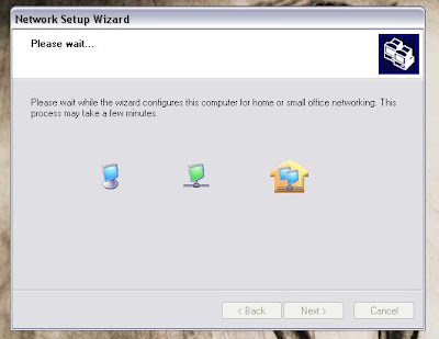
10. Just wait for the network wizard to finish automatic configuration.


Finalizing xp network configuration

11. Just as the XP network configuration will finalize, choose "Just finish the wizard;..." and click "Next"


Confirming to finalize network wizard image

12. Complete the xp networking wizard by confirming through clicking the "Finish" button.


Network wizard restarting computer image

13. Lastly, the xp networking wizard will prompt to restart your computer. Confirm to restart by clicking "Yes".


Checking xp network computers image

14. After having your computer restarted, go to "My Network Places" and click on "View Network Connections". A local network connection indicator (two overlapping computers icon) appears and just click right on it and choose "Properties".


Setting up an ip for network pc image

15. As the LAN Connection box appears, navigate to the "General" tab and highlight "Internet Protocol (TCP/IP) as shown above. As it is highlighted, click on the "Properties" button and the "Internet Protocol (TCP/IP)" properties box should appear.


Assigning ip on xp network computers image

16. Choose the option to "Use the following IP address". Type in the following ip as 192.168.0.1 on one computer and 192.168.0.2 on the second computer. Please do not use the same ip for both computers. The subnet should automatically be filled up as you press the "Tab" space and click "OK" to all confirmations.


IMPORTANT
At this point of the xp home network setup tutorial, I am assuming that you have completed to configure two computers. If you haven't done setting up a home network on the other computer, kindly do it now.


Pinging computers on an XP network image

17. We are almost done on setting up a home network. Xp networking wouldn't be complete if we cannot establish a connection between the computers. To check on how "see" if your computers are able to communicate or has establish a connection, follow this simple pinging procedure.


  • Press Win+R

  • Type in "/ping 192.168.0.2 -t" and press enter. You must ping the ip of the second computer.

    If your computer has an ip of 192.168.0.1, then you must ping the other computer's ip which is 192.168.0.2 and see if it shows something like the image above which concludes a connection is being established.


Checking established computers for xp networking finalization image

18. Let us now verify if we can "see" the computers in our new xp network. Just go to "My Network Places" and as the window should open, you will be seeing the shared documents from the connected computers of your network. Congratulations! You just finished setting up an XP home network.


Setting up a home network is just easy! XP networking as they say, you will be doing the same procedure in setting up a home network in Windows Vista and Win 7. Please comment if something goes wrong with your setup following this tutorial. Networking XP computers will never be as easy! Enjoy your new network and share this wonderful "How to setup a home network" tutorial to your friends.

Crimping Your Own Straight-Through Patch and Crossover Cable


Crimping your first patch or crossover cable for networking may seem hard. But with the proper technique and accurate knowledge, it should be easy as counting 1, 2, and 3. You don't have to memorize certain standard color patterns to be able to crimp your own network cable but we will be discussing about the standard later. There is a quicker way to be able to make a crossover cable fast and easy. I assume you know what a network cable is and decided to make or crimp the cable yourself. However follow the link if you want to have a clearer understanding about home networking. Crimping a patch or crossover cable for networking is an essential skill a computer hardware servicing technician must have. Sometimes, most common computer problems deals with network cables.


T568A and T568B Straight-Through Wiring Diagram


The basic Ethernet pinouts are straight through and cross over. When connecting to switches and hubs, straight through pinout is used. Crossover is used for peer to peer connections for two computers or bridging routers or switches. Relatively, we will be using T568A and T568B diagrams.

For cabling straight through, you can either use T568A or T568B for both ends of the cable. Here is the diagram for you to look as a reference.

This is a T568A Color Pattern

This is a T568B Color Pattern


A patch or straight through is simply crimping two ends of the cable with the same color pattern. If you use one end with T568A color pattern, you must as well use T568A color pattern for the other end. So is the same if you will be using the T568B color pattern respectively. Meaning, there is no need to follow the standard color pattern.

If you will be crimping a crossover cable, just use the T568A on one end of the cable and T568B color pattern on the other end.

I want you to figure out how we crimp crossover cables. If we will be crimping straight-throughs, we use 1-2-3-6 modular connector pin pattern paired to the other 1-2-3-6 modular connector pin pattern.

On the other hand if we will be crimping a crossover cable, we use 3-6-1-2 pin pattern paired to a 1-2-3-6 pin pattern. This method will eliminate memorization of the color patterns which commonly adds confusion in crimping for beginners. Think and figure it out. The diagram provides a clear answer. :-)


Crimping a Network Cat5 Cable with Modular Connector


Materials :

A Length of Unshielded Twisted Pair (UTP) Cat5 Cable

Wire Stripper

Crimping tool (RJ45)

8P8C Modular Connector Plugs or Jacks ("RJ45")

Network Cable Tester


Procedure :


1. Observe computer safety.

2. Remove about 2 inches of the cable's sheath on one end of the Cat5 cable using the wire stripper.

3. Once the sheath is removed, untwist the paired wires. The eight solid wires should be straightened by pressing it down against the table and pushed with another solid material.

4. Align the solid wires and follow either of the color pattern diagrams above.

5. Cut or trim the exposed wires neatly aligned about half an inch.

6. Insert the trimmed wires of the UTP cable into the RJ45 jack following the diagram's direction of the pinouts.

7. Use the crimping tool to set the jack's contacts piercing the 8 strands of wires of the UTP cable. This sinking of the RJ45 "fingers" or "teeth" ensures connectivity for the wires to the jack itself.

8. For the other end, just repeat steps 1 to 6.

9. Verify if your newly crimped cable have perfect connectivity using a LAN cable tester.

If you want to crimp a crossover cable, crimp one end of the cable with the T568A color standard and the other end with the T568B color standard.